Ikea Tradfri - Arduino based Reset- & Pairing-Station
Resetting Ikea Tradfri devices, especially the different lightbulbs, can be annoying. There is an official video showing the process of switching the bulbs on and off six times, but the timing has to be nearly perfect. For me, it works only one out of five times. If you have to reset your entire set of light bulbs or even two or more, you have to be a very calm person… ;)
To make the process of resetting the Tradfri bulbs far easier and the pairing process more convenient, I’ve built a Reset- and Pairing-Station. A real heart-attack saver ;)
The Idea(s)
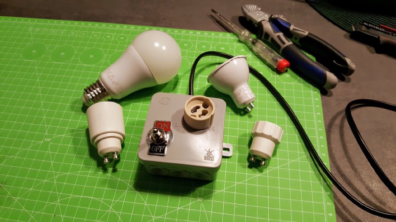
First of all, I had the idea to build a simple box with different lightbulb sockets (E27, GU10, E14) to simplify the pairing process. Since I’m using a Raspberry Pi with a Conbee stick and the Deconz software as a gateway to Home Assistant, I can’t pair the bulbs by holding a Tradfri remote control close to them, so I had to bring the bulbs as close as possible to the Conbee USB stick.
I’ve decided to add a power cord with an integrated switch to simplify the resetting process, but well… okay it is easier than frequently pulling the power plug, but meh…
As already described above, I had some troubles resetting the lightbulbs by hitting the correct frequency. So an additional idea was to add a spare 230V 8A semiconductor relays. With this upgrade, I’m able to switch the power on and off with the help of an Arduino. The perfect tool to automate the resetting process!
What you need
Warning
You are working with 110V/230V!
If you don’t know what you are doing here, or are not qualified to work with this amount of voltage, ask a qualified person for some assistance!
You are risking your and other peoples life!
- 110V/230V Power Cord / Extension Cable
- Flame-retardant Conduit Box
- 150V/250V SSR (e.g. Sharp S202S02)
- Ardunio (or compatible)
- Some lightbulb socket adapters of your choice
And some tools, like a soldering iron, shrinking tubes, hot-glue and cables for the Arduino.
I’m using two conduit boxes here. One for the pairing box and one for the box with the SSR. But you could combine them into one box.
The toggle switch, shown on the pictures, is just a dummy yet.
Step 1: Building the Box
As mentioned above, I am using two boxes, since I had the idea of automating the process after I already built the Pairing Box. You may want to combine both into one box.
1.1 Pairing Box

Dig two small holes with a screwdriver into the cover, where you want to place and insert the wiring of the base adapter (GU10 in my case).
Insert the wiring and hot-glue the adapter to the cover of the box.
Open an entry point for the power cable at the side of the box and insert an end of the power cable. I like to tie a knot into the cable inside the box, so anyone pulling at the cable can’t loosen up or destroy the connections inside, reducing the risk of exposing any voltage.
1.2 Reset Box

You can add this into the Pairing Box or add this as another box between the power cable of your Pairing Box. Since I had one laying around, I’ve used another extension cable to make this more versatile.
Just wire your SSR up as mentioned in your SSRs wiring diagram. In my case, I had to connect my power cord with the pins on the left (~) and the cables for the Arduino on the right (+ and -).
Then you can connect the + and - cables with your Arduino (see below).
You may want to shrink and integrate your microcontroller into your box, but that’s another topic… :)
Step 2: Programming the Arduino

Connect the - pin of the SSR with GND on your Arduino and the + pin with pin 7.
Copy the code (at the end) and upload it to your Arduino.
Programming the Arduino - Step By Step
const int CONTROL_PIN = 7;
boolean resetDone = false;

void setup() {
  pinMode(LED_BUILTIN, OUTPUT);
  pinMode(CONTROL_PIN, OUTPUT);
}
First of all, we define pin 7 as output so we can control the SSR by setting pin 7 to HIGH and LOW.
void blinkStatus(int times) {
  for(int i = 0; i < times; i++) {
      digitalWrite(LED_BUILTIN, HIGH);
      delay(250);
      digitalWrite(LED_BUILTIN, LOW);
      delay(250);
  }
}
The function blinkStatus is a little helper to let the internal LED blink x times each loop starts, to determine if the code is running correctly.
// The following settings worked for GU10 and E27 1000lm lamps:
// off 800ms, on 500ms
void resetTradfriBulb() {
  digitalWrite(CONTROL_PIN, HIGH);
  delay(3000);

  for(int i = 0; i < 6; i++) {
      digitalWrite(CONTROL_PIN, LOW);
      delay(800);
      digitalWrite(CONTROL_PIN, HIGH);
      delay(500);
  }

  resetDone = true;
}
The function resetTradfriBulb does all the magic: First, we enable the lightbulb for three seconds, then, repeating it six times, we disable the lightbulb, wait 800ms and enable it again.
After another 500ms we disable it again for 800ms… and so on, until we repeated it six times and the reset process completed.
You may need to tweak those times, but in my case, they worked with every tested bulb (GU10 and E27).
void loop() {
  blinkStatus(3);

  if (!resetDone) {
    resetTradfriBulb();
  }
}
The loop function is the Arduino’s main method, it will start the reset process when powered on, or after you hit the reset button on the Arduino.
Putting it all together
const int CONTROL_PIN = 7;
boolean resetDone = false;

void setup() {
  pinMode(LED_BUILTIN, OUTPUT);
  pinMode(CONTROL_PIN, OUTPUT);
}

void blinkStatus(int times) {
  for(int i = 0; i < times; i++) {
      digitalWrite(LED_BUILTIN, HIGH);
      delay(250);
      digitalWrite(LED_BUILTIN, LOW);
      delay(250);
  }
}

// The following settings worked for GU10 and E27 1000lm lamps:
// off 800ms, on 500ms
void resetTradfriBulb() {
  digitalWrite(CONTROL_PIN, HIGH);
  delay(3000);

  for(int i = 0; i < 6; i++) {
      digitalWrite(CONTROL_PIN, LOW);
      delay(800);
      digitalWrite(CONTROL_PIN, HIGH);
      delay(500);
  }

  resetDone = true;
}

void loop() {
  blinkStatus(3);

  if (!resetDone) {
    resetTradfriBulb();
  }
}
Usage
Now you have one or two boxes wired up and are ready to reset some Tradfri bulbs. Insert your lightbulb, add some power and tadaa… the Arduino should reset the bulb. :)
Do you have any questions or do you need more details? Just let me know in the comments section.
If you created one yourself, I would love to see them and I am open for additional ideas! :)
Just contact me in the comments or via Instagram.